

Need this roof reviewed?
Prepare commercial roofs in Hollywood, FL for solar arrays, or work around existing ones, with membrane life, mounts, drainage and wind loads planned first.
A solar array and a roof share a lifespan problem. Panels are designed to last for decades, and many membranes are not. If the roof is near the end of its service, the owner faces a hard sequence: install the array and replace the roof later, which means removing and resetting the whole array, or replace the roof first and then install. Where August afternoons sit near 90 degrees and wet-season rain is heavy, both the array and the membrane under it work in a harsh setting. The roof decision comes first.
We evaluate the roof as a platform: its remaining life, structure, drainage, wind resistance and the way each mount will pass through or sit on the membrane. Only then does it make sense to talk about layout.
That order protects the owner from two common mistakes: hanging a new array on a roof that will leak within a few years, and designing a replacement without knowing where the array will stand. A short planning meeting among the owner, the installer and the roofer, held before any equipment is ordered and with the roof sketch on the table, prevents both.
Roof Life Versus Array Life
The first test is remaining service life. We inspect membrane condition, seam strength, flashing, moisture and the repair history. A roof with ample useful life left can host an array without trouble if mounts are detailed well. A roof near the end of its service should be replaced before the array goes in, with a roof replacement that uses a membrane and insulation suited to the added load and traffic.
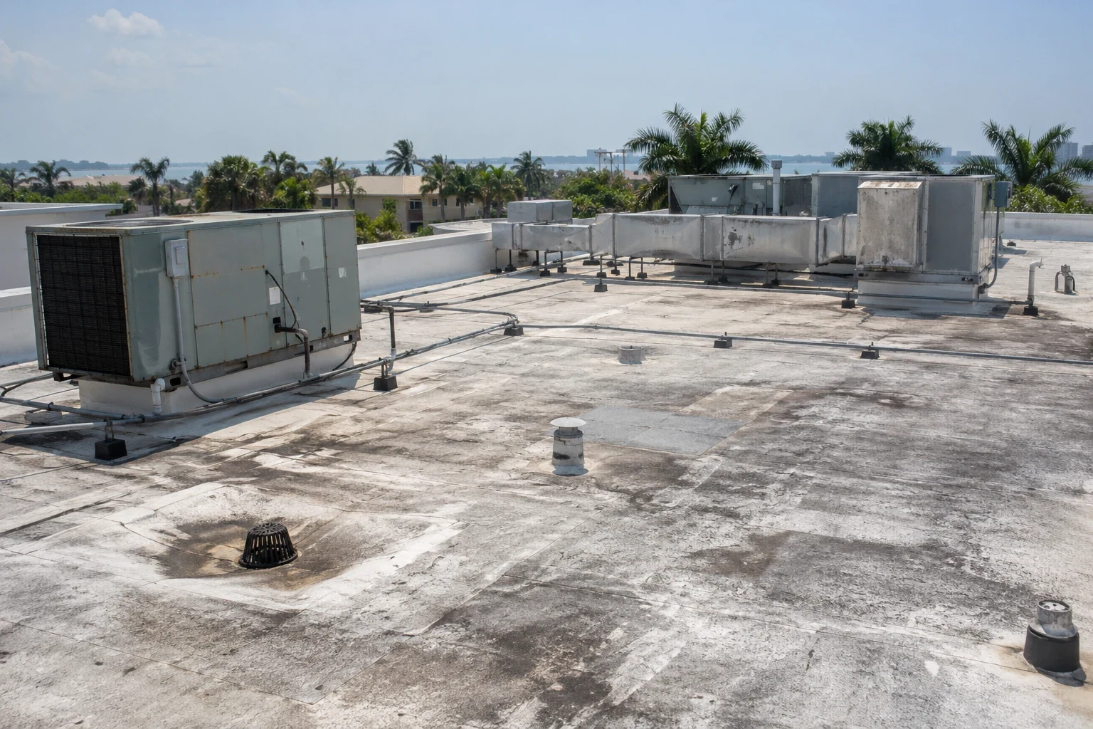
We document the roof condition in a report that an installer, lender or engineer can use, with photographs of every area where a mount, a conduit run or a ballast tray will sit. Our roof condition report format records the membrane type, age if known, moisture findings, structural observations and a recommended path. If the roof is a candidate, the report names the conditions to preserve, such as drainage paths and flashing heights.
Structure and Added Load
Arrays add weight, and wind adds uplift and lateral force. Ballasted systems rest on the roof with concrete or other weight and use little or no penetration. Attached systems fasten to the deck or structure through the membrane and need a flashed penetration at every mount. Hybrid systems combine the two.
Each approach has trade-offs, and neither is automatically better. Ballast adds dead load that the structure must carry and spreads wear across the membrane, and it makes later repairs slower because trays and weights must be moved to reach the surface beneath. Attached mounts reduce load but multiply the number of flashings that must stay watertight, each with its own sealant that will age in the heat. We do not engineer the array or certify structural capacity; that belongs to the engineer of record. We coordinate with the structural engineer and the installer in writing, confirm what the deck is, and design the roof-side details so water stays out.
Mounts, Flashings and Walkways
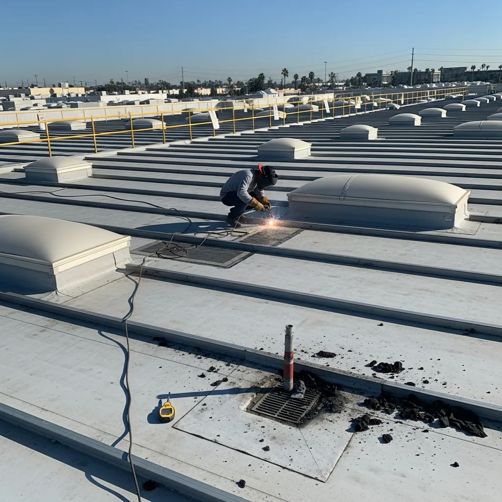
Every attached mount is a penetration, and the flashing detail has to suit the membrane. On a single-ply roof, that may be a prefabricated boot or a welded patch around a post. On modified bitumen, it may be a flashing set in compatible adhesive. On a metal roof retrofit or a standing seam panel, the mount may attach to a seam clamp that avoids penetration altogether.
We specify protection beneath ballast trays, walkway pads along maintenance routes and clear paths between rows. We also check that the array does not block drains, scuppers or access to rooftop equipment. Row spacing leaves room for a person to walk, for water to move and for a lift to reach equipment. Cable trays and conduit are lifted off the membrane on supports, since cables lying on a roof wear through it where they rub or sit in water. Panels shade the membrane beneath, which changes drying and can encourage growth, so we leave gaps for airflow and cleaning where the design allows. Heat is another effect: panels get hot, and the air under them is warmer than open air, so sealants and flashings under an array age differently from those in the open.
Wind, Storm Season and Code
Damaging winds are most likely in South Florida from mid-May into early July, the stormiest phase of the wet season. An array increases the wind exposure of the roof, and the design must account for it. Structural loads are governed by the Florida Building Code, 8th Edition, and Hollywood's building division reviews permitted work for compliance with state and local codes.
Electrical work involves its own permits and inspections, which the array installer handles separately from the roof. We coordinate roof-side permits for the roofing portion and confirm that the work sequence satisfies inspections for both trades.
Sequence deserves a plain description. For a new roof under a new array, the roof goes down first, flashing details for the mounts are installed and tested, the array follows, and a final walk checks every penetration after the installers leave. Foot traffic during array installation is the main risk to a new membrane, so walkway pads and protection boards go down before the first rack is set.
Roofs With Arrays Already in Place
Some roofs already carry arrays installed years ago by other contractors, and the records of those installations can be thin. When a leak appears beneath an array, the repair must work around the panels. We ask the owner or installer for as-built drawings, then trace the water path from the interior stain, inspect mount flashings, check the membrane beneath and between rows and look at drainage. A small repair may need no panel removal, and the file will say which mounts and sections were inspected. A larger one may call for the installer to lift a row, which has to be scheduled with the owner's energy production in mind.
For roofs in the Johnson Street Business District and the Washington Park Industrial Area, where we assume nothing about what is installed, the roof walk records every mount, cable run and pad before a scope is written.
Records That Help Later Work
As-built details shorten every later repair: mount locations, flashing types, ballast layout and walkway routes. Our closeout file records them with photographs and ties them to a maintenance schedule that includes mount flashings, drainage beneath the array and membrane condition at the edges.